Pix4D Mapper Workflow
1. Start
- Launch Pix4D Mapper.
- Click New Project.
- Choose a project name and folder location, then click Next.
- Add your images.
- Click Next.
2. Image EXIF Data Coordinate Transformation
2.1 Export Data from Pix4D
- Click To File.
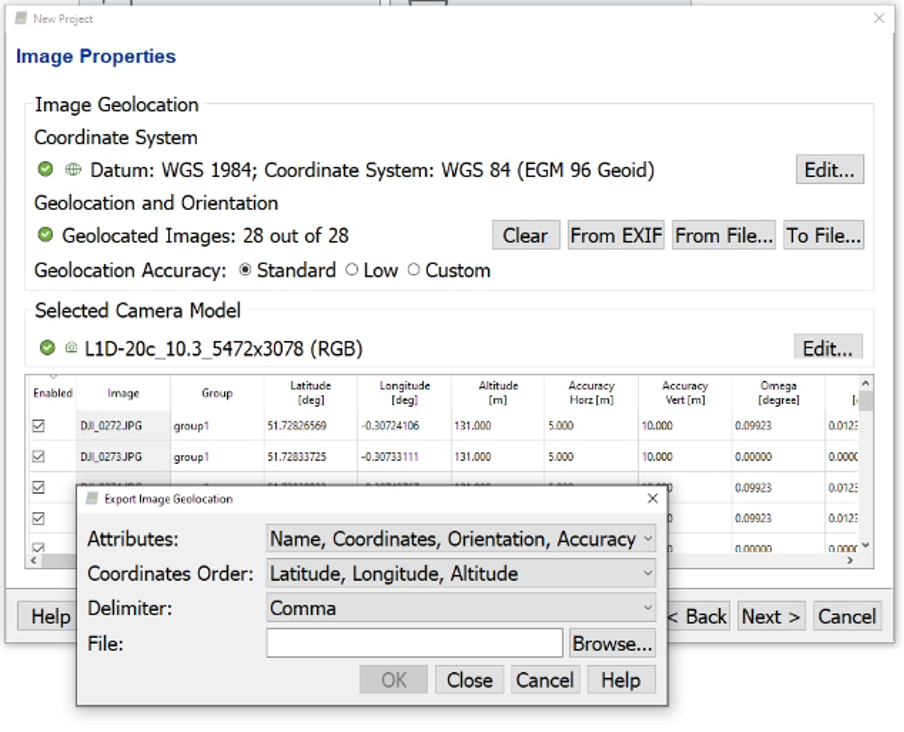
- Choose a file name (e.g. Pix4DExport) and browse to the save location, then click OK. Do not click Next.
- Open the exported text file and copy the data into a new Excel workbook.
- Select the Data tab and click Text to Columns.
- Select Comma as the delimiter.
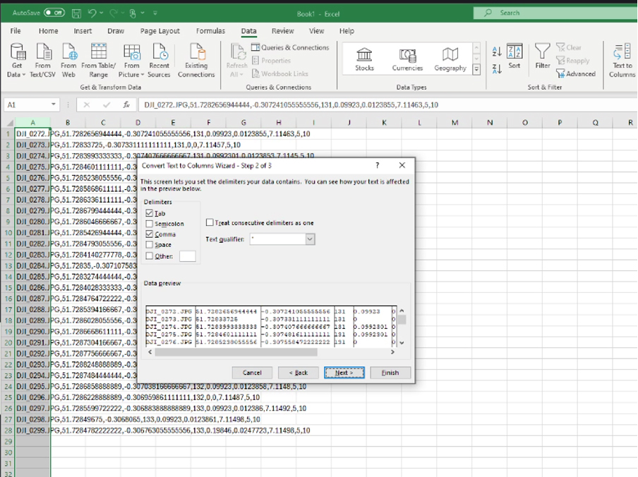
Save the spreadsheet as a CSV file (for example, GridImport.csv).
2.2 Transform Data to OSGB36
- Launch GridInquest.
- Select File → Load Data Points and open the CSV created above.
- Complete the import dialogue, ensuring that the Latitude, Longitude and Altitude columns are mapped correctly.
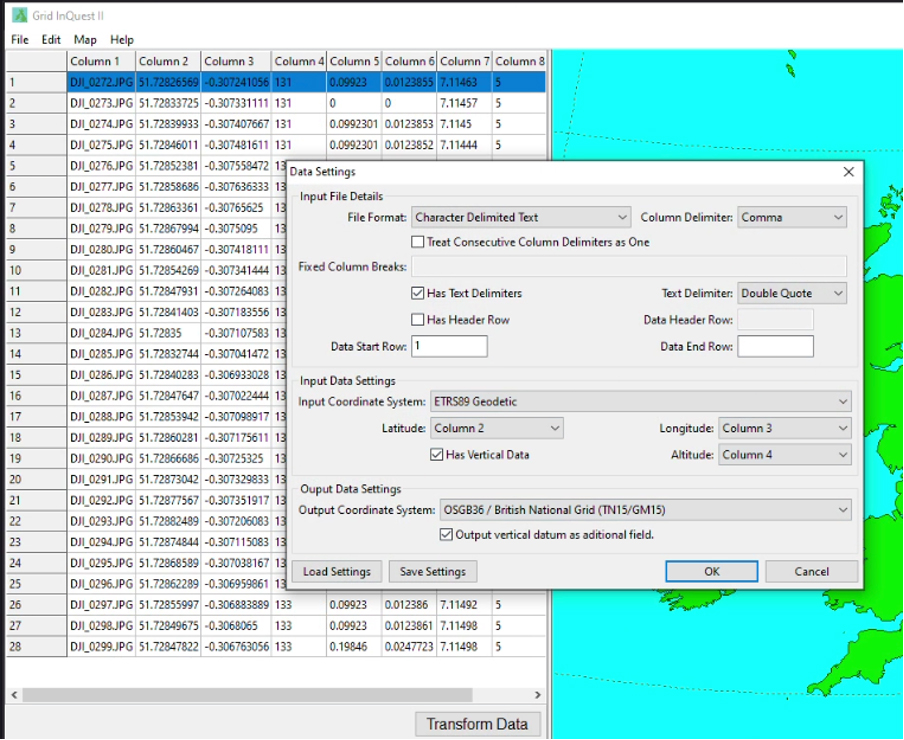
- Click OK, then select Transform Data.
- Select File → Save Data Points and save the transformed file (e.g. GridExport.csv).
- Close GridInquest.
- Open the exported CSV file.
- Copy the three OSGB36 coordinate columns and overwrite the original Latitude, Longitude and Altitude columns.
- Delete the OSGB36-Datum column if present.
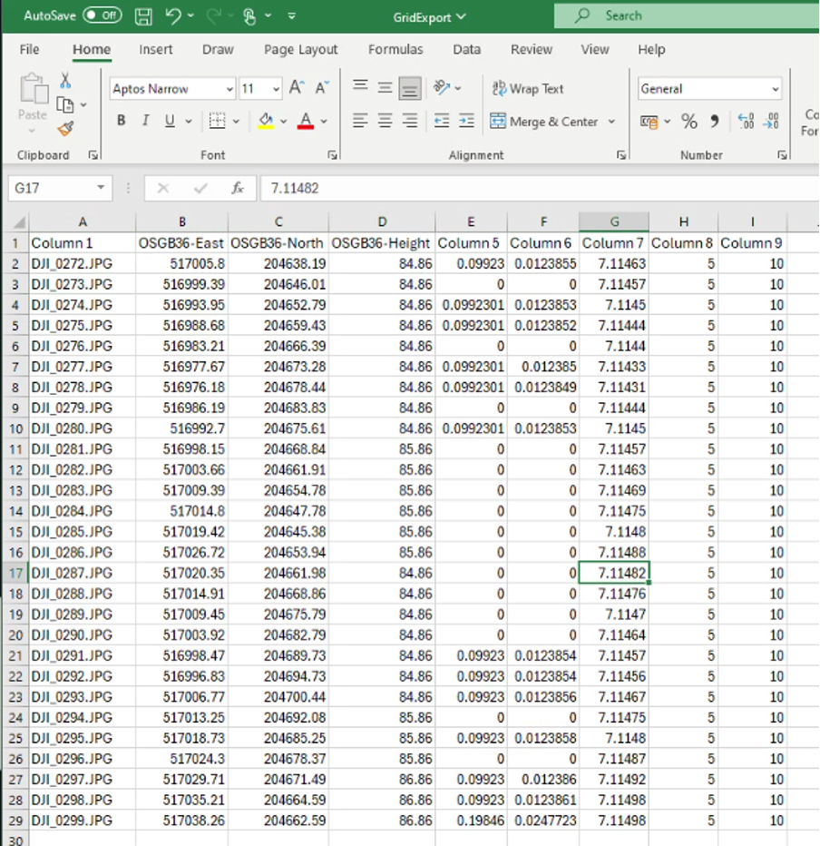
Save the updated CSV file.
2.3 Import OSGB Data into Pix4D
Return to the Image Properties screen in Pix4D.
Edit Coordinate System
- Click Edit (Coordinate System).
- Known Coordinate System: British National Grid.
- Advanced Vertical Coordinate System: Arbitrary.
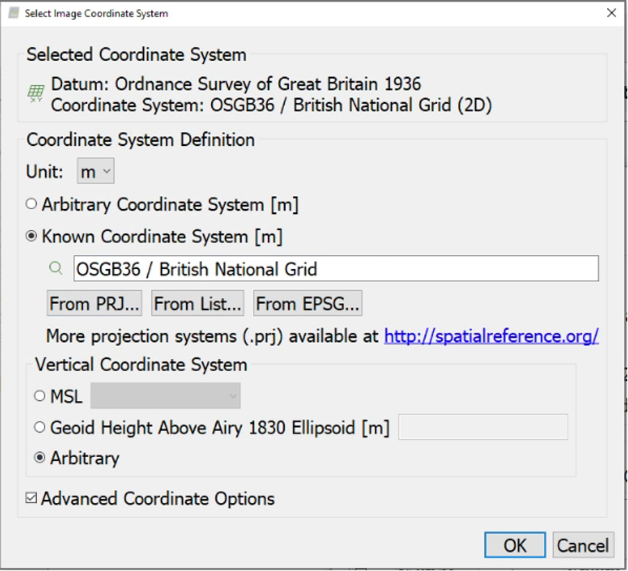
Import Geolocation and Orientation
- Click From File.
- Select the CSV file exported from GridInquest.
- Confirm that the file format settings are correct.
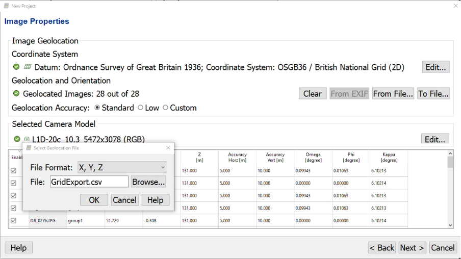
Click OK, then Next. Verify the settings and click Next again.
3. Processing
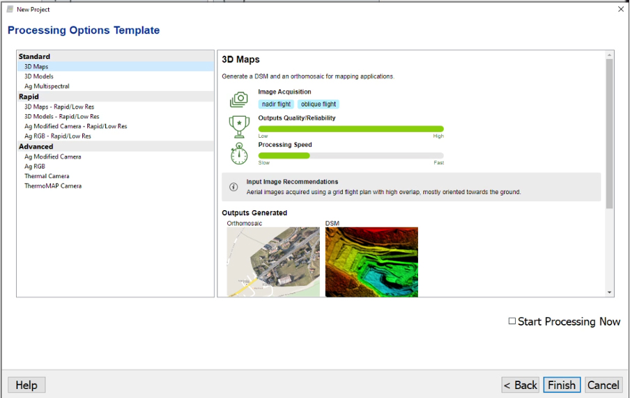
Select the appropriate processing template and untick Start Processing Now, then click Finish.
Select the processing steps you require and click Start.
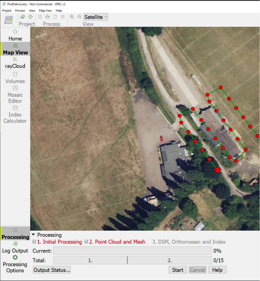
4. Create Processing Area
To be completed.
5. Inputting Ground Control Points (GCPs)
- Open GCP Manager.
- Click Import GCPs.
- Check that the coordinate order is correct.
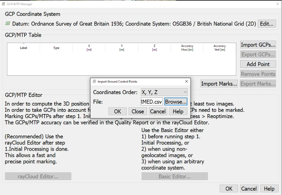
Click OK, then OK again.
5.1 Check GCP Positions
- Open the rayCloud view.
- Select GCPs/MTPs.
- Click Automatic Marking.
- Click Apply.
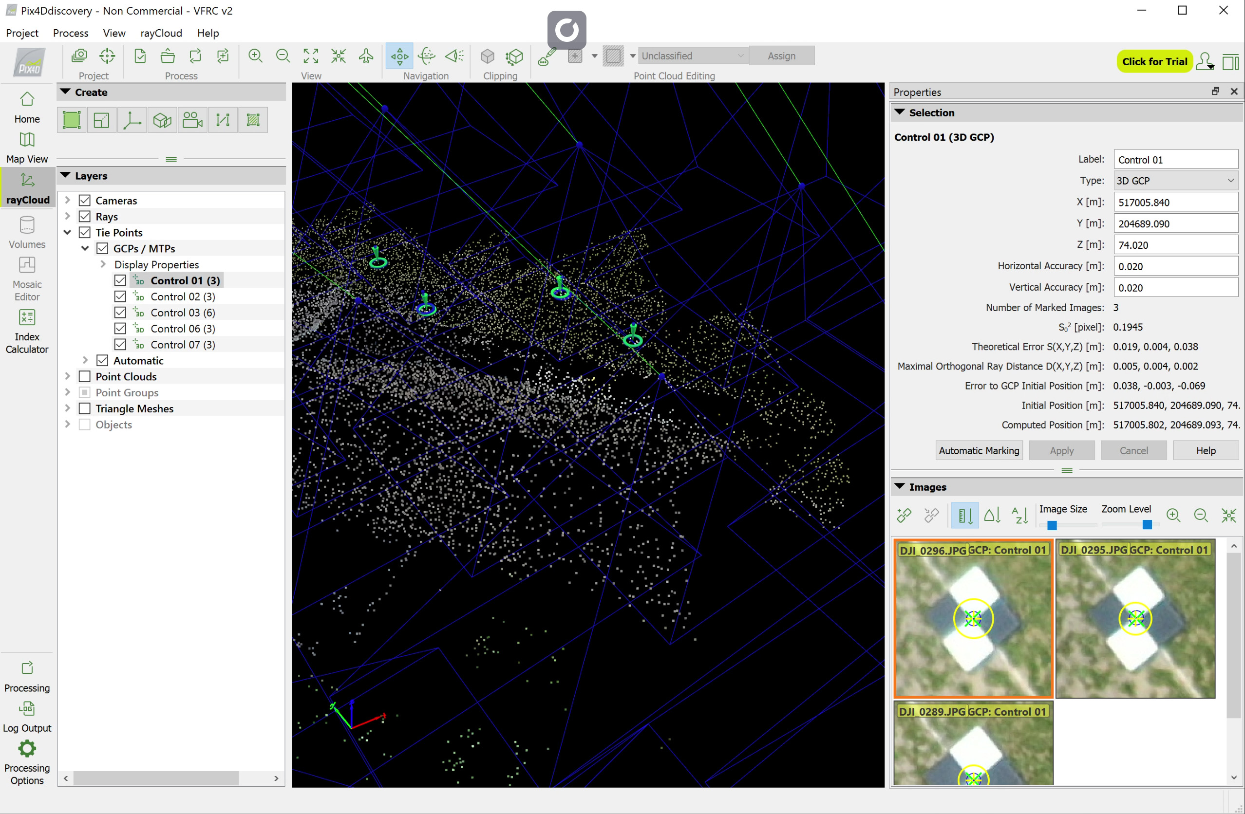
From the Process menu, select Reoptimise.
6. Selection Panel
| Item | Description |
|---|---|
| Label | Custom name assigned to the Ground Control Point or object. |
| Type | Point type, for example 3D GCP. |
| X, Y, Z (m) | Coordinates of the GCP in the project coordinate system. |
| Horizontal / Vertical Accuracy | Known survey accuracy of the GCP. |
| Number of Marked Images | Number of photographs containing that GCP. |
| Σ² [pixel] | Pixel variance of the GCP across marked images. |
| Theoretical Error | Predicted error in the calculated position. |
| Maximal Orthogonal Ray Distance | Maximum deviation between camera rays and the GCP. |
| Error to GCP Initial Position | Difference between surveyed and computed coordinates. |
| Initial Position | Original measured coordinate. |
| Computed Position | Adjusted coordinate after processing. |
| Automatic Marking | Automatically identifies the GCP in all suitable images. |
7. Layers Panel
| Layer | Description |
|---|---|
| Cameras | Displays camera positions and viewing directions. |
| Rays | Shows lines of sight used for photogrammetric triangulation. |
| Tie Points | Automatically matched points used to align photographs. |
| GCPs / MTPs | Ground Control Points and Manual Tie Points used for georeferencing and alignment. |
| Automatic Point Groups | Software-generated groups of related tie points. |
| Point Cloud | Three-dimensional collection of calculated points. |
| Triangle Meshes | Surface model generated from the point cloud. |
| Objects | User-defined or automatically identified objects within the project. |
8. Process Options
Reoptimise
Used after adding or adjusting Ground Control Points, changing coordinates or modifying image markings. Reoptimise recalculates camera positions and point cloud geometry using the updated information.
Rematch and Optimise
This option performs a fresh image matching pass before optimisation. It is particularly useful where image matching was weak or incomplete and can significantly improve overall model quality.